

Pipelines projects require the availability of information about the subsurface along its route, for the civil and electrical designs. Geology comprises a wide range of direct methods of prospecting the soil, as SPT and rotating soundings etc. Geophysics performs these investigations using indirect methods from surface, determining soil parameters through measurement of its physical properties. The interpretation of these measures allows inferring the subsoil structure with costs quite competitive when compared with the direct methods. Among the geophysical methods available, it should be highlighted the Electroresistivity. This technique, by mean of active (injection of electrical currents in the ground) or passive resources (measuring the natural electric and magnetic fields), allows to obtain very accurate models of the subsurface, three-dimensional and with great structure resolution, depicting layers, faults, water table, rocky basement etc. Typically these surveys are conducted early in the project for the civil project. Considering that the electrical engineering design studies need electrical resistivity soil models, for the specification of cathodic protection, for interference studies where the duct line crosses with transmission lines and also for the design of
grounding systems for pumping stations, “city gates” and other installations along the duct route, it is suggested in this paper the integration of geophysical surveys conducted for the civil and electrical engineering, in a single measurement campaign. This integration will result on lower costs with geophysical surveys, considering that the measuring teams will go to field only once. It must also be considered that the same equipments are used for the entire set of measurements. An additional benefit is that geophysics companies are usually more qualified for this type of survey, than the small companies that typically measure soil resistivity for electrical design, usually limited to small spacing Wenner measurements, which was the only one recognized by the former version of NBR-7117, specific code for the measurement of soil resistivity for electrical projects. This code has undergone extensive review and in its new 2012 version, supports a wide range of geophysical resources for conducting soil resistivity measurements and soil modeling.

GEOPHYSICAL SURVEYS FOR PIPELINE DESIGN INTEGRATED SUBSOIL MAPPING FOR THE CIVIL AND ELECTRICAL PROJECTS
Paulo Edmundo da F. Freire1,Edgar Pane2,Suzana Domingues3
Copyright 2013, Brazilian Petroleum, Gas and Biofuels Institute – IBP
This Technical Paper was prepared for presentation at the Rio Pipeline Conference & Exposition 2013, held between September, 24-26, 2013, in Rio de Janeiro.
1. Introduction
Oil, ethanol and gas pipelines, among others, are welded steel tubes distributed over hundreds of kilometers, crossing different geological environments, subject to corrosion, electrical and electromagnetic interference. Beyond the different soil characteristics and environments along its path, the pipeline passes by installations that are part of its operational infrastructure and, also, close to other independent facilities, which may interfere with the pipeline operation and integrity, due to proximity effects.
Among the facilities that constitute the operational infrastructure of the pipeline network, it should be mentioned maneuver and pumping stations, city-gates and rectifiers of the cathodic protection system. Among other facilities that may be in the path of the pipeline, and that will interact with it, it should be pointed the crossings with power lines, electrified railroads, proximity to electrical substations and interconnections with industrial facilities.
In the first case, the facilities that make up the infrastructure of the pipeline will be the object of specific projects, including the civil and electrical designs. For planning the pipeline route, it will be needed the knowledge of the soil characteristics.
The electrical design will require the specification of cathodic protection systems and the design of grounding systems and lightning protection. In the case of installations which will interact with the pipeline, studies shall be carried out to quantify the possible interference voltages which may be induced on the pipelines, both in normal or abnormal operation condition.
In all the above cases, it will be needed the measurements of soil electrical resistivity, and the development of soil models, for the execution of the studies and projects associated with each situation.
2. Electrical Projects
The development of the activities below presented, always starts with the construction of the electrical equivalent circuit, including the transmission line, substation, groundings grids and pipeline. For the calculation of the parameters of this electrical circuit – grounding resistances (self and mutual), transmission line impedances and mutual impedances between transmission line and buried ducts – it will be needed the knowledge of the soil model.
2.1 Cathodic Protection Systems
The rectifiers and its anodes, for the cathodic protection system, are distributed along the pipeline route. For the design of this system it will be needed the soil resistivity measurements at the places where the sacrificial anodes will be buried. A shallow soil model is enough for this purpose.
2.2 Grounding Grid and Lightning Protection Design
Most of the installations associated with the pipeline operation (city gates and valve stations) do not depend on local supervision by operators, relaying on remote supervision and operation. These installations need a reliable infrastructure, which includes power supply, grounding and lightning protection.
The grounding grid must be designed in compliance with many codes, as it will attend both the electrical installation and the lightning protection system. It is desirable for the grounding resistance a value below 10 Ohms. If the installation is feed by a medium-voltage distribution line, than the specific codes for this kind of installation asks also for the calculation of the step and touch voltages, concerning personal security. The knowledge of the soil resistivity will be needed for the calculation of the ground resistance and for the step and touch voltage evaluations.
2.3 Interference Studies for Industrial Pipeline Entrances
Industrial plants very often have the medium or high voltage substation located near the pipeline entrance, in the utilities area. If a phase to ground short-circuit occurs in the substation, the pipeline and its measuring gate at the plant entrance, may be exposed to high voltage ground potential rise, of about a few kilovolts. The coupling of the substation with the pipeline entrance may be due to a direct connection between the grounding grids, or due to resistive coupling, if these two grids are separated but close to each other.
The consequences of this situation are reflected in various risks, with emphasis on:
- damage to the protective coating of the duct, due to the increased soil potential, in excess of its dielectric supportability (typically on the order of 5kV);
- damage to cathodic protection system components, such as rectifier and insulating joints at gas entrance; and
- potentially hazardous touch voltages on exposed parts of the duct (valves, measuring equipment etc.).
The interference studies related to this kind of situation are developed by means of the modeling of the grounding grid of the entire industrial plant, together with the incoming pipeline and transmission line, and with the simulation of phase-to-ground short-circuit at the substation high-voltage bus bar.
The control of the soil-duct overvoltage, in order to protect the insulating covering and also to avoid dangerous touch voltages on exposed parts, will be obtained by means of the redesign of the whole industrial grounding grid, complemented by the specification of surge suppression devices. Usually a few scenarios will be simulated before it is found the best grounding grid configuration, with options of separated and/or interconnected grids.
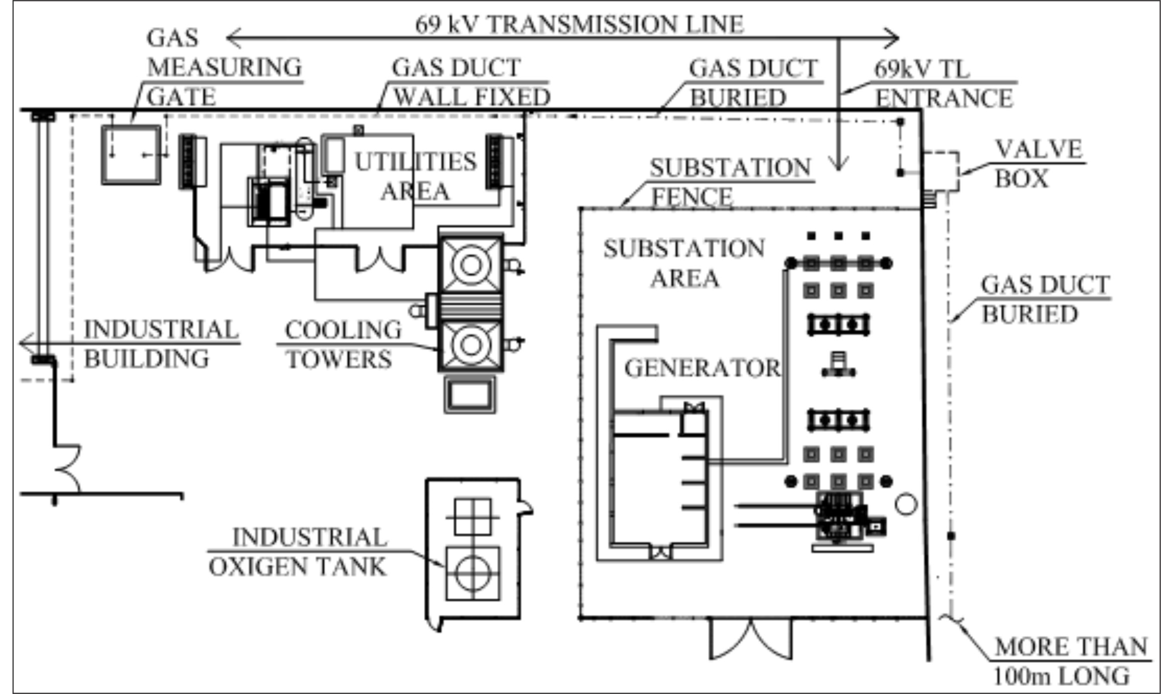
Figure 1: typical gas entrance on factory utility area, where it can be seen a 69 kV transmission line and substation very close to the pipeline and gas measuring gate.
2.4 Interference Studies for Substation Proximity and Transmission Line Crossing
Substation and transmission line interference with steel structures involves three types of couplings, namely, inductive, resistive and capacitive.
The inductive coupling is characterized by the occurrence of longitudinal voltages on the phases and neutral of medium and low voltage distribution lines, on the shielding and pairs of telephone lines and on long metal structures parallel to the transmission line, resulting from unbalanced currents in the LT.
The resistive coupling is characterized by the occurrence of voltages on the grounding of transformers, on the neutral of distribution lines, on the screening and suspension cables of telephone lines, and on metal grounded structures (pipelines and fences), due to current injection on grounding of power system elements, such as meshes of substation grounding and foundations of transmission lines towers.
These two types of couplings may result in critical situations with the occurrence of phase to ground failure in the electrical system, due to the high unbalanced currents of the transmission line, which interact with the interfered installations, causing the occurrence of high voltages.
The capacitive coupling is characterized by the occurrence of static voltages on not grounded metallic structures, such as pipelines and structures in assembly or maintenance condition, when portions of them, next to substations and transmission lines, are not in contact with the ground, creating a risk situation to personnel safety.
3. Geophysical Surveys
Geophysics is based on the physical phenomena occurring inside Earth, associated to Earth’s magnetic field; propagation of seismic waves, gravity, electromagnetic and electric fields; telluric currents, and; radioactivity. The methods of gravimetry and magnetometry are natural field, studying disturbances that certain structures or bodies produce on existing fields. The geoelectrical methods (except for the spontaneous potential and magnetotelluric) and seismic are artificial, what means that the physical field to be studied is created by means of appropriate equipment.
The theoretical fundaments of geophysical methods are based on the determination of physical properties that characterize the different types of materials found in geological environment, and on the contrasts these properties may present. The characteristics of different geological materials define the geophysical method to be applied. Each method is intended to characterize and identify different properties of geological materials, according to the research purpose.
Investigation techniques, to study the variation of physical parameters of geological materials, both at field and in laboratory, one can take three forms of investigative practices:
- variations of the physical parameter in depth, from a fixed point on the soil surface;
- lateral variation from points not fixed at soil surface, with one or more fixed depths; and
- borehole profiling.
For the development of the surveys, different field procedures can be adopted, related to the configuration of electrodes needed to perform the measurements, and are called development arrangements, which feature a wide variety of options. It is not possible to establish superiority relations between different geophysical methods, since the efficiency of each method depends on the type of terrain to be prospected and model of soil to be obtained. Among the methods available it shall be pointed
- electroresistivity – oriented to near-surface surveys, is a method of “artificial field” produced by applying voltage difference to ground, and
- magneto-telluric – oriented to deep surveys, is a method of “natural field”, that needs a big distance (minimum 1km) from facilities in general.
Methods of natural fields are susceptible to interference, which limit its application close to urban and industrial areas. The electroresistivity method uses four electrodes aligned, two current electrodes and two potential probes, with various arrangements, which result in different mapping capabilities of soil resistivity, namely:
- electric sounding – when for the same point, the exploration of variation vertical (depth) of soil resistivity;
- electrical profiling – when the object of interest is the study of lateral variation in resistivity, maintaining a constant depth theoretically.
Among the possible arrangements of the four electrodes are:
- Wenner and Schlumberger – where the current electrodes are external and the voltage probes are internal, most commonly used for vertical electrical sounding, and
- dipole-dipole – with the current and voltage electrodes grouped two by two, that lends itself to sounding and electrical profiling.
The combination of these methods with appropriate variations of spacing allows obtaining three-dimensional soil models of excellent quality. The presented geophysical methods do not exclude the surface geological mapping, interpretation of local lithography, and possible mechanical soil surveys, to obtain a better geological model of a particular area.
4. Geophysical Surveys Planning
Information about the physical environment along the pipeline route are needed, to support planning and civil projects. This information can be obtained by means of direct methods in geotechnical engineering, such as SPT and rotating well drilling surveys, integrated with indirect methods of applied geophysics, such as seismic, electric and electromagnetic methods. This way, one can obtain a complete geotechnical profile throughout all the pipeline route, with information regarding the geotechnical context, such as the soil type and classification – category 1 (soil), category 2 (rock alteration) and category 3 (bedrock), morphological and physical characteristics of the bedrock, natural frequency of oscillation, and preliminary evaluation of main technical soil parameters of interest to builders, such as Young’s modulus, Poisson coefficient etc.
Usually the route geologic/geophysical survey will be developed in the very beginning of the pipeline project. As soon as the route has been defined, the soil survey database can be enriched with the complementary surveys needed for the other projects, mainly the electrical projects and the interference studies.
For each application, a specific complementary geophysical survey will be required. For instance, soil resistivity for cathodic protection systems only probe shallow soil layers, with current electrodes usually below 25m. For interference studies and grounding grid design, a much deeper survey shall be needed, with current electrodes spacing of up to 1000m. It is important to note that when we specify a depth of survey, actually we are meaning probes spacing at soil surface. For the Wenner arrangement, the depth of survey will be at maximum 1/3 of the current electrodes spacing.
5. Examples of Geophysical Surveys
The examples below show some results of electroresistivity soil surveys.

Figure 2: electric 2D imaging by dipole-dipole electrode arrangement – 10 meters wide current and potential probes with 5 levels of dept investigation – determination the alteration mantle thickness of the granitic massif.

Figure 3: soil sections for pipeline construction design.

Figure 4: soil resistivity mapping at 63,5m, obtained by 2D electrical imaging of lines G0, G1, G2, G3, G4 and G5, by means of dipole-dipole arrangement, with AB = MN = 50m and 6 levels of depth investigation.
6. References
Paulo Edmundo Freire, Daniel Kovarsky – “Cuidado com a Resistência de Aterramento das Hastes nas Medições de Resistividade do Solo”, seminário GROUND98 (Belo Horizonte, mai/98);
Paulo Edmundo Freire – “Aterramento de Subestações – os Critérios da Futura Norma Brasileira” – XI ENIE – Encontro Nacional de Instalações Elétricas (SP, jun/2006);
Paulo Edmundo Freire – “Substation Interference on Gas Entrance of Industrial Plants”, congresso do IBP – Instituto Brasileiro de Petróleo – Rio Pipeline 2009 (set./2009, RJ);
Paulo Edmundo Freire – “Aterramento de Subestações – Nova Norma 15.751/2009” – ENIE 2010 – Encontro Nacional de Instalações Elétricas (SP, jun/2010).
Paulo Edmundo Freire, Roberto Menna Barreto – “Diretrizes para o Projeto do Sistema de Aterramento em Instalações de Automação e Controle” – ENIE 2012 – Encontro Nacional de Instalações Elétricas (SP, agosto/2012).
Paulo Edmundo Freire, Edgar Pane e Newton Guaraldo – “Aterramento de Parques Eólicos”, WindPower 2012 (RJ, agosto/2012).
Paulo Edmundo Freire, Edgar Pane e Newton Guaraldo – “Techniques for the Study of Large Industrial Grounding Systems”, Rio Oil&Gas 2012 (RJ, setembro/2012).
Paulo Edmundo Freire, Edgar Pane e Newton Guaraldo – “Electrical Grounding – a Field for Electrical Engineers and Geophysicists Partnership”, AGU – American Geophysical Union – Fall Meeting 2012 (San Francisco, CA, dezembro/2012).
Notes about the authors
1Paulo Edmundo da F. Freire
Degree in Electrical Engineering and a Master in Power Systems, both from the Pontifical Catholic University of Rio de Janeiro. Currently direct the company ELETRO-ESTUDOS Engenharia Elétrica Ltda, which is a consulting firm in electrical engineering.
2Edgar Pane
Degree in Geology, Geophysics specialization with emphasis on electrical methods. MSc in geophysics applied to hydrogeology area. Over the last thirty years direct the company GEOANALISYS Consultoria Geofísica Ltda, which provides geophysical consulting applied to mining, geotechnical, hydrogeology and environment.
3Suzana Domingues
Degree in Environmental Engineering. Presently works in company GEOANALISYS Consultoria Geofísica Ltda as a project manager.
